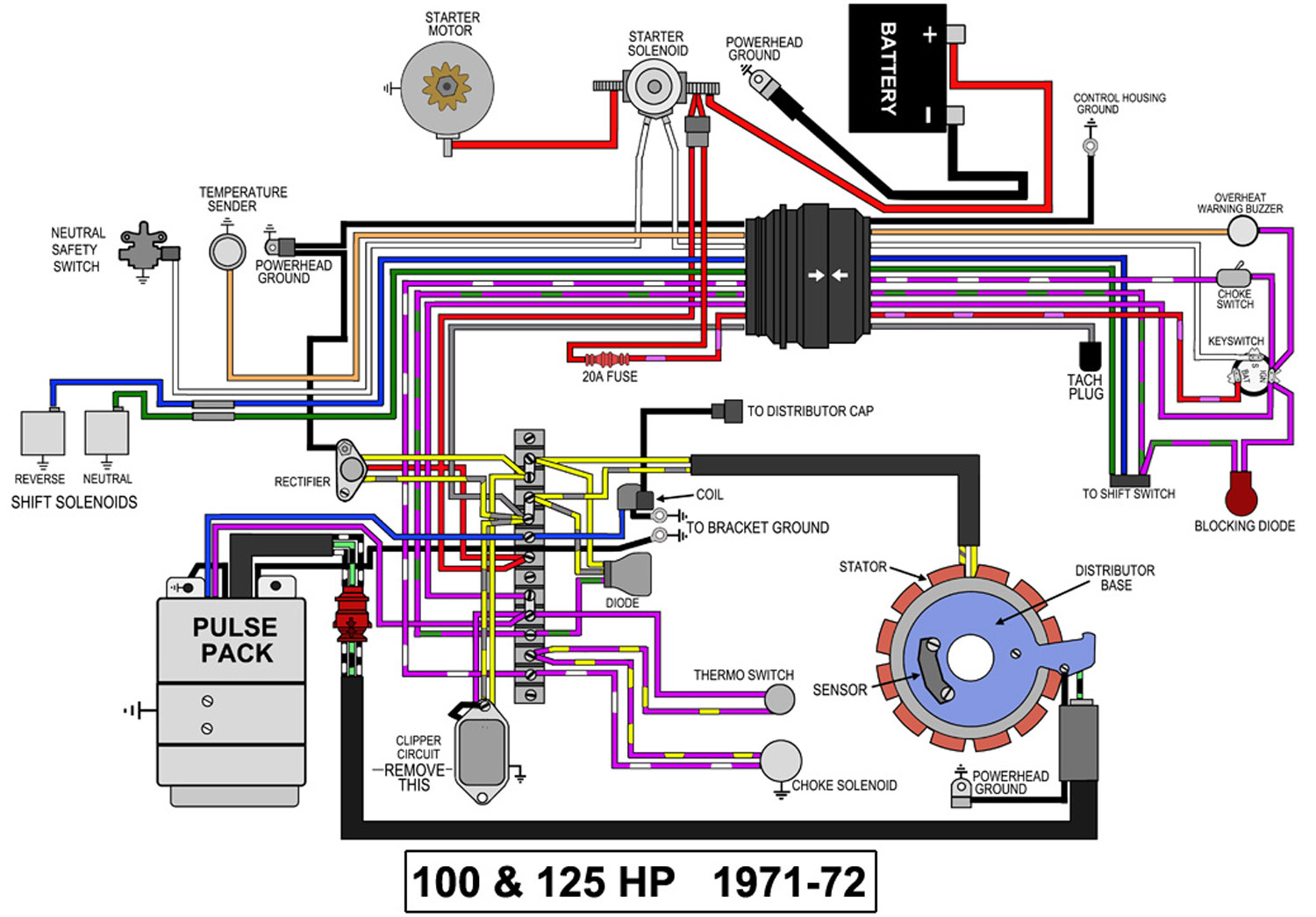
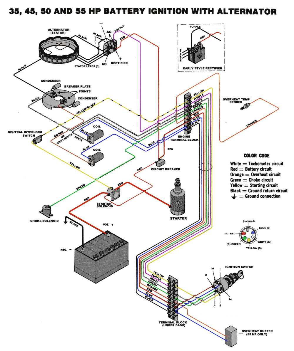
Johnson Ignition Switch Wiring Diagram is a crucial tool for anyone working on the electrical system of a Johnson outboard motor. This diagram provides a visual representation of the wiring connections and layout of the ignition switch, making it easier to understand and troubleshoot any issues that may arise.
Why are Johnson Ignition Switch Wiring Diagrams Essential?
Johnson Ignition Switch Wiring Diagrams are essential for several reasons:
- Helps in understanding the wiring connections of the ignition switch
- Assists in troubleshooting electrical issues
- Ensures proper installation and maintenance of the ignition system
How to Read and Interpret Johnson Ignition Switch Wiring Diagrams
Reading and interpreting Johnson Ignition Switch Wiring Diagrams may seem daunting at first, but with a little guidance, it can become much easier:
- Refer to the legend or key provided in the diagram for understanding symbols and colors
- Follow the wiring paths and connections from the ignition switch to various components
- Pay attention to the numbering or lettering used for each wire for proper identification
Using Johnson Ignition Switch Wiring Diagrams for Troubleshooting
Johnson Ignition Switch Wiring Diagrams are invaluable when it comes to troubleshooting electrical problems in the ignition system:
- Identify the specific wire or connection that may be causing the issue
- Check for continuity and proper voltage flow using a multimeter
- Compare the actual wiring with the diagram to spot any discrepancies
Importance of Safety
When working with electrical systems and using wiring diagrams, it is crucial to prioritize safety:
- Always disconnect the battery before working on any electrical components
- Use insulated tools to prevent electrical shocks
- Avoid working in wet or damp conditions to prevent electrical hazards
By following safety tips and best practices, you can ensure a safe and successful experience when working with Johnson Ignition Switch Wiring Diagrams.
Johnson Ignition Switch Wiring Diagram
Johnson Outboard Ignition Switch Wiring Diagram

Johnson Ignition Switch Wiring Diagram – Cadician's Blog

Johnson Outboard Ignition Wiring Diagram

Johnson Outboard Ignition Switch Wiring Diagram – Hanenhuusholli

Johnson Outboard Ignition Switch Wiring Diagram – Collection
50 Hp Johnson Wiring Diagram
