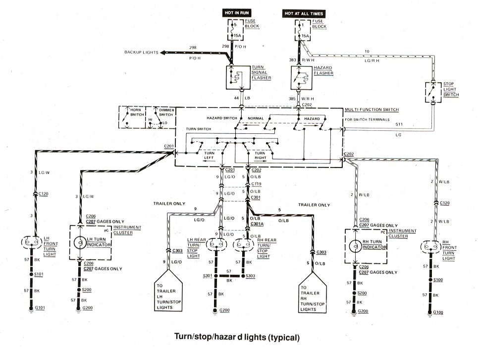
When it comes to understanding and diagnosing electrical issues in a Ford vehicle, having access to a Ford Ignition System Wiring Diagram can be incredibly helpful. This diagram provides a detailed layout of the ignition system wiring, allowing mechanics and DIY enthusiasts to trace electrical connections, locate components, and troubleshoot problems effectively.
Why are Ford Ignition System Wiring Diagrams Essential?
Understanding the wiring diagram for the ignition system in a Ford vehicle is essential for several reasons:
- Identifying the location of key components such as the ignition coil, starter solenoid, and ignition switch.
- Tracing the flow of electricity through the system to diagnose issues such as no-start conditions, misfires, or electrical shorts.
- Ensuring proper connection and continuity of wires to prevent electrical malfunctions or safety hazards.
How to Read and Interpret Ford Ignition System Wiring Diagrams
Reading and interpreting a Ford Ignition System Wiring Diagram may seem daunting at first, but with a systematic approach, it can be straightforward:
- Start by familiarizing yourself with the symbols and color-coding used in the diagram.
- Identify the key components and their corresponding wires in the diagram.
- Follow the path of the wiring to understand how electricity flows through the system.
- Use a multimeter to test for continuity and voltage at various points in the system.
Using Ford Ignition System Wiring Diagrams for Troubleshooting
When faced with electrical problems in a Ford vehicle, a wiring diagram can be a valuable tool for troubleshooting:
- Locate the affected circuit in the diagram and trace the wiring to identify potential issues such as loose connections, damaged wires, or faulty components.
- Compare the actual wiring in the vehicle to the diagram to pinpoint discrepancies or modifications that may be causing the problem.
- Refer to the wiring diagram to understand the function of each wire and component, helping to diagnose the root cause of the issue.
Importance of Safety When Working with Electrical Systems
Working with electrical systems, including using wiring diagrams, requires a cautious approach to ensure safety:
- Always disconnect the battery before working on any electrical components to prevent the risk of electrical shock or short circuits.
- Use insulated tools and wear appropriate safety gear such as gloves and goggles when handling electrical connections.
- Avoid working on electrical systems in wet or damp conditions to reduce the risk of electric shock or damage to components.
Ford Ignition System Wiring Diagram
[DIAGRAM] 1970 Ford Mustang Ignition Wiring Diagramfor – MYDIAGRAM.ONLINE
![Ford Ignition System Wiring Diagram [DIAGRAM] 1970 Ford Mustang Ignition Wiring Diagramfor - MYDIAGRAM.ONLINE](http://1.bp.blogspot.com/-Mz7Y-QbpQis/USnFzzphhVI/AAAAAAAAAvs/J43dChxWRyI/s1600/Ignition+1.jpg)
Ford Ranger Ignition Wiring Diagram – Wiring Diagram
Ignition Wiring Diagram Ford F150

Ford Ignition System Wiring Diagram

2003 Ford Ranger 3.0 Ignition System Wiring Diagram

Part 1 -Ignition System Circuit Diagram (1994-1995 Ford F150, F250, F350)
