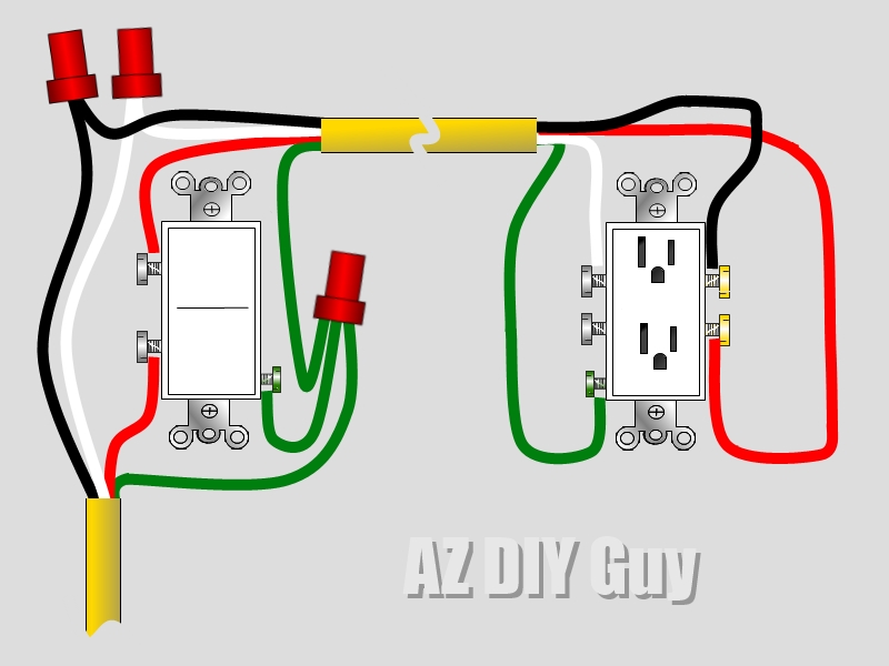
Electrical Receptacle Wiring Diagrams are essential tools for understanding and visualizing the electrical connections in a receptacle. These diagrams provide a clear and detailed illustration of how the wires are connected and where they should be placed. By following a wiring diagram, electricians and DIY enthusiasts can ensure that their electrical work is done correctly and safely.
Importance of Electrical Receptacle Wiring Diagrams
- Ensure proper wiring connections
- Prevent electrical hazards
- Comply with electrical codes and regulations
- Facilitate troubleshooting and repairs
Reading and Interpreting Wiring Diagrams
When reading an Electrical Receptacle Wiring Diagram, it’s important to understand the symbols and abbreviations used. Each wire is represented by a different color and line style, making it easy to differentiate between them. The diagram will also include labels for each connection point, indicating where each wire should be attached.
Using Wiring Diagrams for Troubleshooting
Electrical Receptacle Wiring Diagrams are invaluable for troubleshooting electrical problems. By referencing the diagram, you can quickly identify any incorrect connections or faulty wiring. This can help you pinpoint the source of the issue and make the necessary repairs or adjustments.
Safety Tips for Working with Electrical Systems
- Always turn off the power before working on electrical systems
- Use insulated tools to prevent electric shock
- Double-check all connections before energizing the circuit
- Wear appropriate safety gear, such as gloves and goggles
- Avoid working on electrical systems in wet or damp conditions
By following these safety tips and using Electrical Receptacle Wiring Diagrams, you can ensure that your electrical work is done safely and correctly. Whether you’re installing a new receptacle or troubleshooting an existing one, these diagrams are invaluable tools for anyone working with electrical systems.
Electrical Receptacle Wiring Diagram
Wiring Diagram For A Switched Receptacle

Home Outlet Wiring Basics – Wiring Flow Line
/wiring-electrical-receptacle-circuits-through-a-receptacle-1152787-01-2a9a43dca2d04d6597dcfb791a548ff9.jpg?strip=all)
Understanding Electrical Receptacle Wiring: A Comprehensive Diagram Guide

Understanding Electrical Receptacle Wiring: A Comprehensive Diagram Guide

Wiring Up A Receptacle

Understanding Electrical Receptacle Wiring: A Comprehensive Diagram Guide
