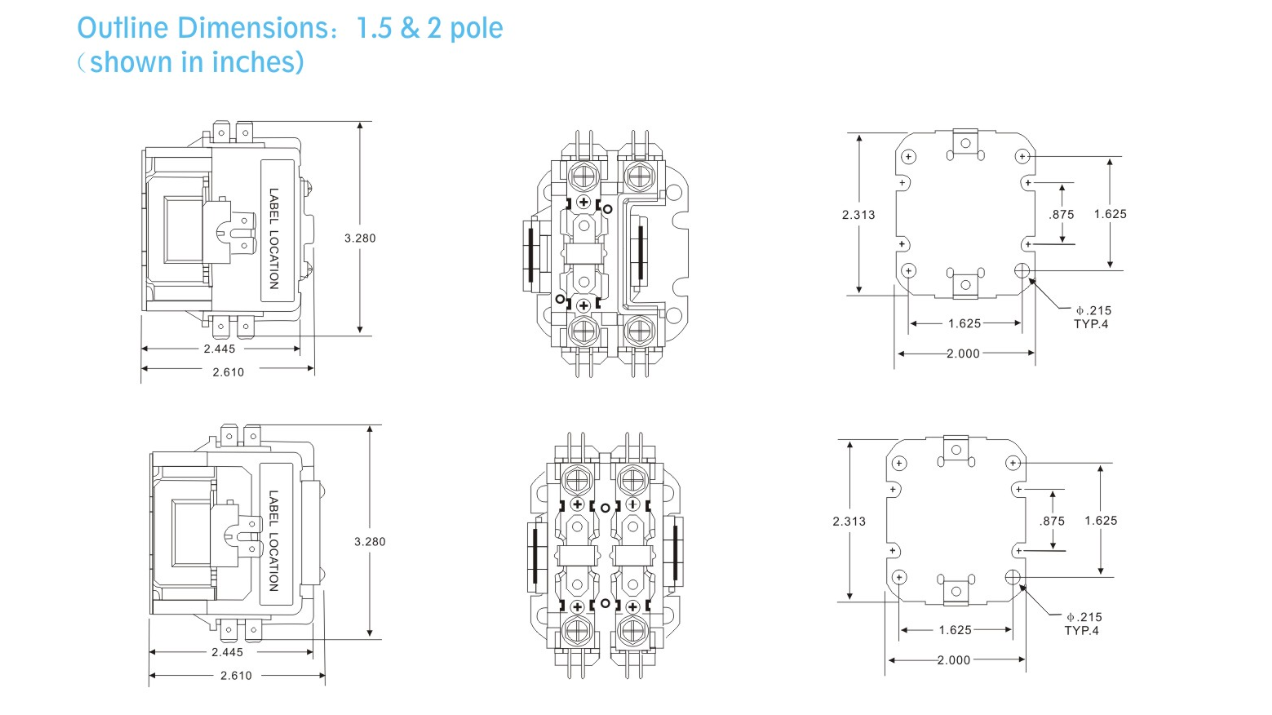
When it comes to electrical systems, having a clear and accurate wiring diagram is crucial for ensuring everything functions properly. A Definite Purpose Contactor Wiring Diagram is a detailed schematic that outlines the connections and components of a definite purpose contactor, which is used to control electric motors, heating elements, lighting, and other electrical loads.
Importance of Definite Purpose Contactor Wiring Diagrams
Definite Purpose Contactor Wiring Diagrams are essential for various reasons:
- They provide a visual representation of how the contactor is wired, making it easier to understand the connections.
- They help ensure that the contactor is installed correctly, reducing the risk of electrical malfunctions or hazards.
- They serve as a reference guide for troubleshooting and maintenance, allowing technicians to quickly identify and resolve issues.
Reading and Interpreting Definite Purpose Contactor Wiring Diagrams
When reading a Definite Purpose Contactor Wiring Diagram, it’s important to pay attention to the following:
- The symbols and color codes used to represent different components and connections.
- The direction of current flow and the sequence of operations for the contactor.
- The labeling of terminals and wires to ensure proper connectivity.
Using Definite Purpose Contactor Wiring Diagrams for Troubleshooting
Definite Purpose Contactor Wiring Diagrams are valuable tools for troubleshooting electrical problems:
- They help identify potential issues with connections, components, or wiring that may be causing malfunctions.
- They guide technicians in tracing the flow of current and pinpointing the source of a problem.
- They assist in making informed decisions on repairs or replacements based on the diagram’s information.
Safety Tips for Working with Wiring Diagrams
When working with electrical systems and using wiring diagrams, it’s essential to prioritize safety:
- Always turn off the power supply before inspecting or working on any electrical components.
- Use proper insulation tools and equipment to prevent electrical shocks or short circuits.
- Double-check connections and follow the diagram accurately to avoid errors or misinterpretations.
- Seek assistance from a qualified electrician if you are unsure about any aspect of the wiring diagram or electrical work.
Definite Purpose Contactor Wiring Diagram
How to Wire an Eaton Definite Purpose Contactor: A Step-by-Step Wiring

How To Connect A Contactor Diagram – Wiring Draw And Schematic
Wiring Diagram For Definite Purpose Contactor » Wiring Digital And

30 Definite Purpose Contactor Wiring Diagram – Wire Diagram Source

How to Wire an Eaton Definite Purpose Contactor: A Step-by-Step Wiring

Definite Purpose Contactor Wiring Diagram Best Of | Wiring Diagram Image
