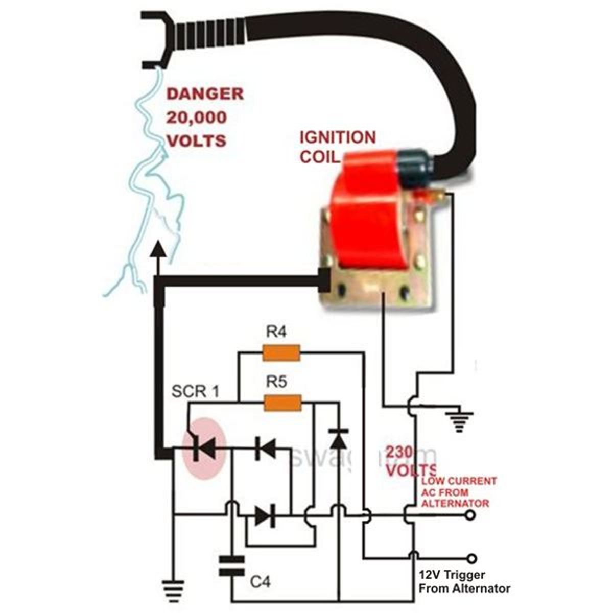
Understanding the Cdi Ignition Wiring Diagram is crucial for any mechanic or enthusiast looking to troubleshoot or repair their ignition system. This diagram provides a visual representation of the electrical connections and components involved in the CDI ignition system, allowing for easier identification of any issues.
Why Cdi Ignition Wiring Diagrams are Essential
- Helps in understanding the layout of the ignition system
- Aids in identifying faulty connections or components
- Facilitates troubleshooting and repairs
Reading and Interpreting Cdi Ignition Wiring Diagrams
When looking at a CDI ignition wiring diagram, it’s important to pay attention to the symbols and color codes used. Here are some key points to keep in mind:
- Follow the flow of the diagram from the power source to the components
- Identify the different wires and their functions based on the legend provided
- Note any junctions or connections that may be potential areas for issues
Using Cdi Ignition Wiring Diagrams for Troubleshooting
CDI ignition wiring diagrams are invaluable when it comes to diagnosing electrical problems in the ignition system. Here’s how you can make the most of them:
- Trace the wiring to locate any loose connections or damaged wires
- Check the continuity of the wires and components using a multimeter
- Compare the diagram to the actual wiring to ensure everything matches up
Safety Tips for Working with Cdi Ignition Wiring Diagrams
When working with electrical systems and wiring diagrams, safety should always be a top priority. Here are some tips to keep in mind:
- Always disconnect the power source before working on any electrical components
- Use insulated tools to prevent electrical shocks
- Avoid working in wet or damp conditions to reduce the risk of electrocution
Cdi Ignition Wiring Diagram
5 Pin CDI Wiring Diagram (Pictured AND Explained!) – Off-Road Official

Polaris CDI Wiring Diagram (Pictured & Explained) – Off-Road Official

CDI Ignition kit for Maico 400 | Electrex World

Wiring Diagram For Cdi Ignition

Basic Ignition Wiring Diagram With Cdi

Cdi Ignition Wiring Diagram
