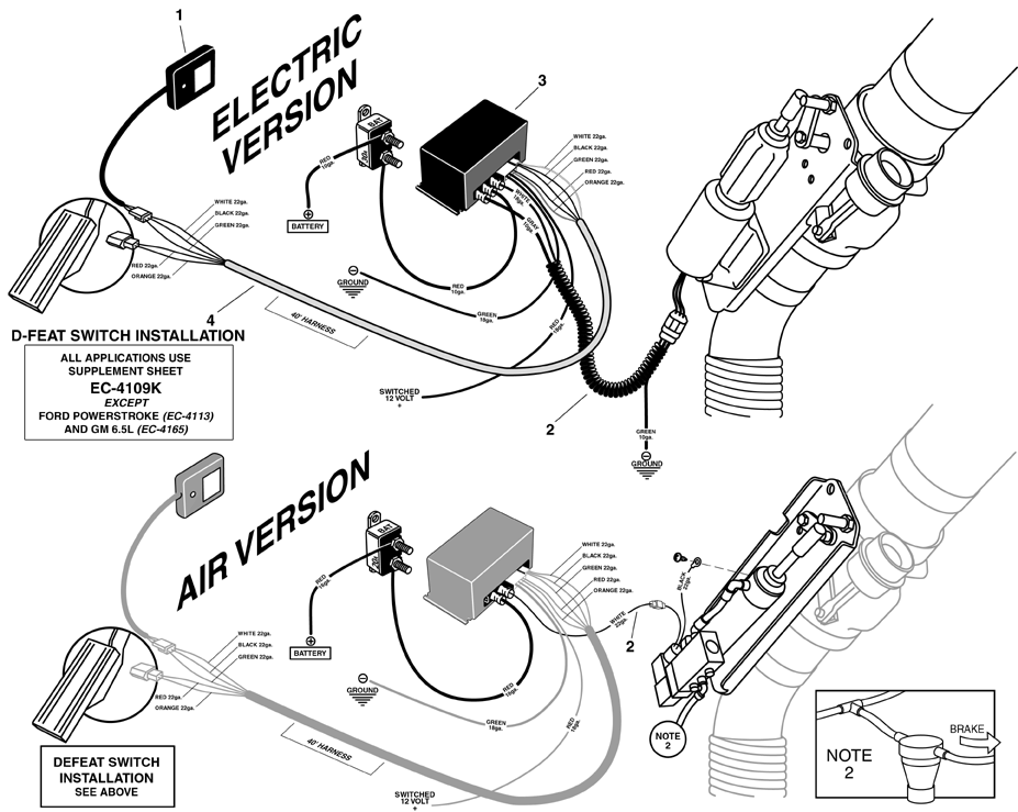
Brake Motor Wiring Diagrams are essential tools for understanding the electrical connections in brake motors. These diagrams provide a visual representation of how the various components of the motor are connected and help ensure proper installation and maintenance.
Why Brake Motor Wiring Diagrams are Essential
Brake Motor Wiring Diagrams are essential for several reasons:
- Ensure proper installation of brake motors
- Help troubleshoot electrical issues in brake motors
- Provide a reference for maintenance and repairs
Reading and Interpreting Brake Motor Wiring Diagrams
When reading a Brake Motor Wiring Diagram, it’s important to understand the symbols and markings used. Here are some key points to keep in mind:
- Identify the components of the motor, such as the brake, motor windings, and control circuit.
- Follow the flow of electricity through the diagram to understand how the motor operates.
- Pay attention to the color-coding of wires to ensure proper connections.
Using Brake Motor Wiring Diagrams for Troubleshooting
Brake Motor Wiring Diagrams can be invaluable when troubleshooting electrical problems in brake motors. By following the wiring diagram, you can:
- Locate and inspect potential points of failure in the electrical system.
- Trace the flow of electricity to identify where a circuit may be interrupted.
- Compare the actual wiring connections to the diagram to pinpoint any discrepancies.
Safety Tips for Working with Brake Motor Wiring Diagrams
When working with electrical systems and using wiring diagrams, it’s crucial to prioritize safety. Here are some important safety tips to keep in mind:
- Always turn off power to the motor before inspecting or making any changes to the wiring.
- Use insulated tools to prevent electrical shock.
- Wear appropriate protective gear, such as gloves and safety glasses, when working with electrical components.
- If you’re unsure about any aspect of the wiring diagram or electrical system, consult a qualified electrician.
Brake Motor Wiring Diagram
Engine Brake Wiring Diagram – Wiring Diagram and Schematics

Clutch Brake Motor Connection Diagram Rectifier Module – YouTube

Motor brake rectifier connection diagram | Engineers CommonRoom

brake motor wiring diagram
Engine Brake Wiring Diagram – Wiring Diagram and Schematics
